Understanding what's actually happening inside an engine control unit is the difference between guessing and diagnosing. This reference guide takes you inside the printed circuit board of dozens of widely-used diesel and gasoline ECU platforms, breaking down exactly what each component does and why it matters.
What's Inside PCB ECU COMPONENT FUNCTIONS
This guide covers 80+ ECU board variants, spanning early-generation diesel control units through modern common-rail and gasoline management systems — including well-known EDC7, EDC15, EDC16, EDC17, ME7, ME9, ME17, MED17, and MP-series platforms found across a wide range of vehicle brands.
For each board, you'll find:
- Full PCB layout diagrams showing the physical placement of every major component
- Component-by-component breakdowns — microcontrollers, power ICs, driver stages, voltage regulators, protection circuits, integrated sensor interfaces, filtering capacitors, and relays
- Functional explanations of how each block operates within the overall control system, so you understand the "why" behind the wiring — not just the "where"
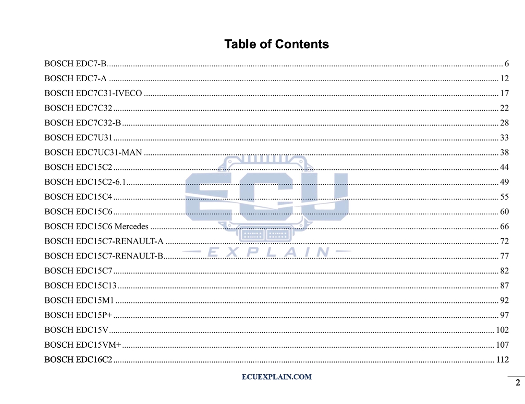
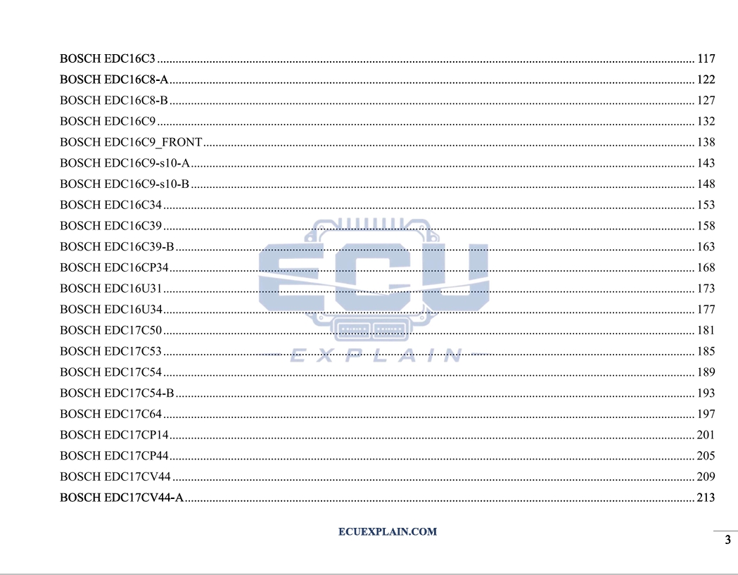
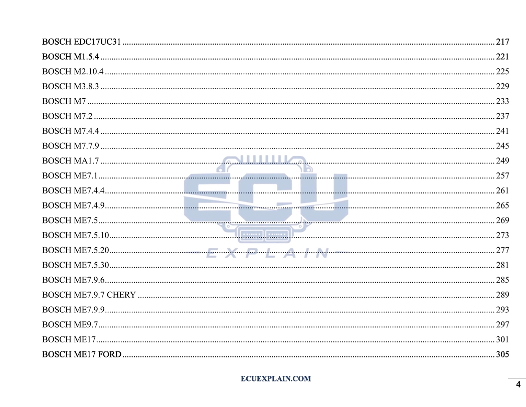
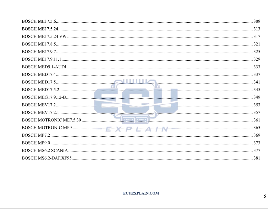
Who This Is For?
- ECU repair and reflashing technicians
- Auto electrical diagnostic centers
- Automotive mechatronics students and engineers
- Anyone reverse-engineering or troubleshooting engine control hardware
Why It Matters
Repairing an ECU without a clear map of its internals means relying on trial and error — probing components blindly and hoping for the best. This guide replaces that guesswork with a structured, board-by-board reference. Instead of spending hours tracing circuits from scratch, you can look up the exact board layout, pinpoint the component responsible for a given function, and move straight to testing or replacement.
Whether you're diagnosing a no-start condition, chasing an intermittent sensor fault, or rebuilding a damaged control unit, this guide gives you the internal knowledge needed to work with precision and confidence.