INSIDE ECU PCB: Understand Every Component is a technical manual focused on automotive ECU hardware and PCB component analysis. The book goes beyond basic ECU identification. It examines the electronic structures that control processing, power management, memory, signal transmission, and actuator operation.
The material covers ECU architectures from Continental, Siemens, Delphi, Magneti Marelli, Motorola, and selected OEM platforms including Toyota, Nissan, Renault, Volkswagen, and Scania. It is designed for technicians, ECU specialists, automotive electronics professionals, and learners who want to understand ECU hardware at component level.
What Does INSIDE ECU PCB Cover?
The manual focuses on identifying and understanding the core electronic components found on complex ECU PCBs.
- MCU architecture and identification.
- Infineon TriCore and Motorola MCUs.
- Voltage regulator circuits.
- EEPROM and Flash memory.
- Crystal oscillator circuits.
- ECU signal flow.
- TVS diode protection.
- Electrolytic, tantalum, and ceramic capacitors.
- MOSFET and IGBT drivers.
- Multi-driver ICs.
- Injector control circuits.
- Ignition coil drivers.
- Electronic throttle control.
- Relay control circuits.
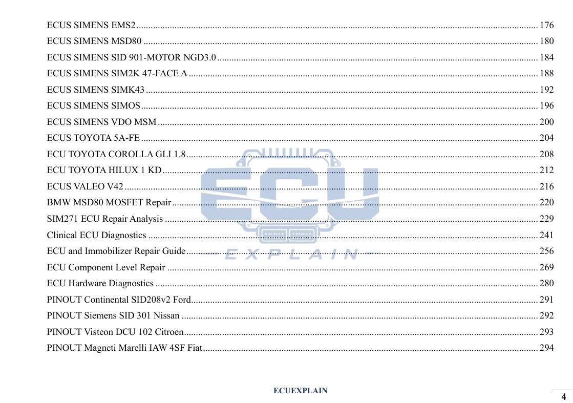
- ECU pinout analysis.
- Important voltage measurement points.
The content connects individual components with their roles inside the complete ECU circuit.
Which ECU Platforms Are Discussed?
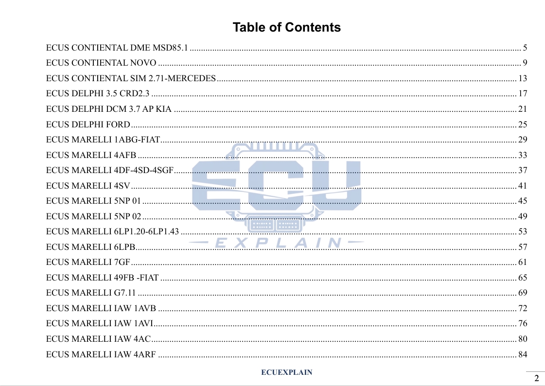
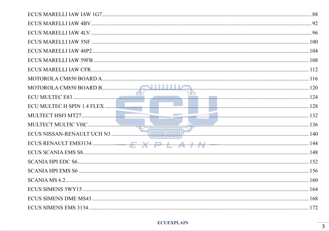
The manual covers multiple ECU families from major Tier-1 suppliers and OEM platforms.
- Continental
- Siemens
- Delphi
- Magneti Marelli
- Motorola
- Multec
- Valeo
- Toyota
- Nissan
- Renault
- Volkswagen
- Scania
The coverage is based on the ECU families and examples included in the manual.
It should not be interpreted as universal compatibility with every ECU produced by these manufacturers.
Which ECU Components Will You Learn?
The book focuses on several component groups that form the foundation of ECU electronics.
MCU – Microcontroller Unit
The MCU is the central processing component of an ECU.
The manual examines MCU identification and architecture, including Infineon TriCore and Motorola examples.
Readers can connect the MCU with surrounding power, memory, input, and output circuits.
EEPROM and Flash Memory
EEPROM and Flash are important memory technologies used within ECU systems.
The manual explains their position within ECU architecture and their relationship with the control electronics.
Voltage Regulators
Voltage regulation provides controlled electrical supply to different ECU circuits.
The manual examines voltage-processing structures and important measurement nodes.
Crystal Oscillators
Crystal oscillators provide timing references for electronic circuits.
Their identification is included as part of the ECU PCB component analysis.
How Does ECU Signal Flow Work?
ECU signal flow describes how electrical information travels through different circuit stages.
The manual follows signal paths from input circuits toward the central processing stage and output circuits.
A simplified structure can be understood as:
Sensor Input → Protection → Filtering → Signal Processing → MCU → Driver → Actuator
The exact circuit depends on the ECU architecture being analyzed.
The book also discusses components used in protection and filtering, including:
- TVS diodes.
- Electrolytic capacitors.
- Tantalum capacitors.
- Ceramic capacitors.
This approach helps technicians understand how individual PCB components contribute to the complete signal path.
How Are ECU Actuator Drivers Analyzed?
Actuation drivers connect ECU processing logic with physical vehicle components.
The manual examines driver circuits used for functions such as:
- Fuel injectors.
- Ignition coils.
- Electronic throttle bodies.
- Auxiliary relays.
Relevant semiconductor components include:
- MOSFETs.
- IGBTs.
- Multi-driver ICs.
The material also includes an electronic throttle example using an H-Bridge configuration with TLE6209R.
This provides a practical reference for understanding how an ECU can control an electric actuator through a dedicated driver stage.
What Can You Learn From ECU Pinout and Voltage Analysis?
Pinout and voltage analysis help connect the ECU PCB with its external electrical connections.
The manual introduces practical analysis of:
- Power supply connections.
- Ground connections.
- Signal inputs.
- Signal outputs.
- Communication connections.
- Actuator-related circuits.
- Important electrical nodes.
Voltage measurement can help technicians investigate whether a circuit is receiving appropriate electrical conditions.
Measurements must always be interpreted according to the specific ECU circuit and technical reference.
How Can ECU PCB Analysis Support Repair and Programming?
PCB analysis provides hardware knowledge that can complement ECU diagnostics, repair, and programming work.
A diagnostic fault does not always identify the physical component responsible for a problem.
Component-level analysis can provide another layer of investigation.
The manual helps readers understand relationships between:
- ECU power circuits.
- MCU architecture.
- Memory.
- Signal paths.
- Driver stages.
- Actuators.
- Pinouts.
- Measurement points.
This knowledge can support further work involving ECU repair, data intervention, programming, and calibration.
Actual results depend on the ECU hardware, failure condition, software, equipment, and technician experience.
Who Is This ECU PCB Manual For?
The manual is intended for readers who want to develop deeper knowledge of automotive ECU electronics.
It can be useful for:
- ECU repair technicians.
- Automotive diagnostic technicians.
- ECU programming specialists.
- Automotive electronics technicians.
- ECU tuning professionals.
- PCB repair technicians.
- Workshop technicians.
- Automotive technical learners.
It is particularly relevant to readers who want to understand ECU hardware rather than relying only on diagnostic software.
What Will You Learn From This Manual?
The manual develops a structured understanding of ECU PCB architecture and component-level analysis.
- Identify common ECU PCB components.
- Understand MCU structures.
- Recognize EEPROM and Flash memory.
- Analyze voltage regulation circuits.
- Trace ECU signal flow.
- Identify protection components.
- Analyze MOSFET and IGBT driver stages.
- Understand injector and ignition driver circuits.
- Examine electronic throttle driver architecture.
- Read ECU pinout information.
- Identify important voltage measurement points.
- Connect PCB components with ECU functions.
The manual uses a practical, workbench-oriented approach to connect electronic theory with ECU hardware analysis.
Why Study ECU Electronics at Component Level?
Component-level knowledge helps technicians understand what happens inside an ECU.
Modern ECU diagnostics can involve both software and hardware.
Software tools can provide fault codes, identification data, and diagnostic information. PCB analysis provides a different perspective by examining the physical electronic circuits behind ECU functions.
Understanding both perspectives can help technicians build a more complete approach to ECU troubleshooting.
The goal is not simply to recognize a component. It is to understand its function, connections, and relationship with the surrounding circuit.
Frequently Asked Questions
What is INSIDE ECU PCB: Understand Every Component?
It is a technical manual focused on ECU PCB architecture, electronic components, signal flow, power circuits, memory, and actuator drivers.
Which ECU components are covered?
The manual covers MCUs, voltage regulators, EEPROM, Flash, crystal oscillators, protection components, MOSFETs, IGBTs, and driver ICs.
Does the manual cover Infineon TriCore?
Yes. Infineon TriCore is included in the MCU analysis.
Does it cover ECU signal flow?
Yes. The material examines signal transmission from input circuits through processing stages and toward actuator drivers.
Does it cover ECU repair?
The manual provides component-level knowledge relevant to ECU hardware analysis and repair-oriented work.
Who should study this manual?
It is suitable for ECU technicians, diagnostic specialists, programmers, automotive electronics technicians, and technical learners.
Study ECU PCB Architecture With AutoExplain
Understanding ECU electronics requires more than identifying a control unit by its part number.
INSIDE ECU PCB: Understand Every Component focuses on the components and circuit structures inside complex automotive ECUs.
The manual covers MCU architecture, memory, voltage regulation, signal flow, protection circuits, actuator drivers, pinouts, and voltage measurement concepts across multiple ECU platforms.
For technicians working with ECU diagnostics, repair, programming, or automotive electronics, this manual provides a structured foundation for studying ECU hardware at component level.
Explore INSIDE ECU PCB: Understand Every Component and develop a deeper understanding of modern automotive ECU electronics with AutoExplain.